
Built on a foundation of networking knowledge, MAAS introduces a number of new terms, and adds some nuances to common terms. Some of these terms may be common networking terms you never looked up; others represent more complex concepts that may be unique to MAAS. This article presents and explains some of these important terms.
Show me an alphabetical list of terms
- Availability zones
- Client
- cloud-init
- Controller
- Device
- DHCP
- DHCP relay
- Edge clouds
- Fabrics
- Hub
- Images
- Interfaces
- isolcpus
- LAN
- MAC address
- Machine
- Machine actions
- Machine statuses
- MAN
- Network cable
- Network infrastructure
- Network interface
- Network topology
- NUMA
- Nodes
- Package repositories
- Packet
- Patch panel
- Regions
- Repeater
- Router
- Series
- Server
- Spaces
- SR-IOV
- Subnets
- Switch
- Tags
- Ubuntu package repositories
- VLAN
- VM hosts
- WAN
Nodes
A node is a general term that refers to multiple, more specific objects. Nodes are managed by MAAS through a life cycle, from adding and enlistment into MAAS, through commissioning, allocation and deployment. Nodes are then either released back into the pool of nodes or retired.
Nodes include three classes of objects:
- Controllers
- Machines
- Devices
See Machine actions and Machine statuses below for an overview of a node’s life cycle.
Controllers
There are two types of controllers: a region controller and a rack controller. The region controller deals with operator requests while one or more rack controllers provide the high-bandwidth services to multiple server racks, as typically found in a data centre.
A region controller consists of five components:
- REST API server (TCP port 5240)
- PostgreSQL database
- DNS
- caching HTTP proxy
- web UI
Think of a region controller can as being responsible for a data centre, or a single region. Multiple fabrics are used by MAAS to accommodate subdivisions within a single region, such as multiple floors in a data centre.
A rack controller provides four services:
- DHCP
- TFTP
- HTTP (for images)
- power management
A rack controller is attached to each “fabric”. As the name implies, a typical setup is to have a rack controller in each data centre server rack. The rack controller will cache large items for performance, such as operating system install images, but maintains no independent state other than the credentials required to talk to the region controller.
Both the region controller and the rack controller can be scaled-out as well as made highly available.
Machines
A machine is a node that can be deployed by MAAS.
Devices
A device is a non-deployable node. This entity can be used to track routers, for example.
Static or dynamic IP addresses and DNS names can be assigned to any device or parent node. These addresses will be automatically deleted when the parent node is deleted or released, along with any IP address reservations. This arrangement is designed to model and manage the virtual machines or containers running inside a MAAS-deployed node.
VM hosts
VM hosts, also called composable hardware, allow for the dynamic composition of machines from a pool of available hardware resources (e.g. disk space, memory, cores).
Zones
A physical zone, or just zone, is an organisational unit that contains nodes where each node is in one, and only one, zone. Later, while in production, a node can be taken (allocated) from a specific zone (or not from a specific zone). Since zones, by nature, are custom-designed (except for the ‘default’ zone), they provide more flexibility than a similar feature offered by a public cloud service (ex: availability zones).
Some prime examples of zone usage include fault-tolerance, service performance, and power management.
A newly installed MAAS comes with a default zone which contains all nodes unless you create a new zone. You can therefore safely ignore the entire concept if you’re not interested in leveraging zones.
You cannot remove the ‘default’ zone or change its name.
Regions
A region is an organisational unit one level above a zone. It contains all information about all machines running in any possible zones. In particular, the PostgreSQL database runs at this level and maintains state for all these machines.
Series
A series is essentially an operating system version. For Ubuntu, a series takes into account HWE kernels. In practical terms, a series manifests itself in the form of install images that are used to provision MAAS machines. The MAAS administrator can select series as desired.
Images
An image is used to provision a machine. As soon as you install MAAS, images are imported based on what series you have selected. MAAS won’t work until it has imported the necessary images.
Fabrics
A fabric connects VLANs. If you understand a VLAN, you know that they permit network connections only between specific switch ports or specifically identified ports (“tagged” ports). Consequently, it would be impossible for two VLANs to communicate with each other. A fabric makes these VLAN-to-VLAN connections possible.
Take me on a quick, deep dive on fabrics
We can illustrate a network fabric more easily by rewinding the term to one of its earliest uses: the early phone system. In a telephone switchboard, subscriber lines (customer phone numbers) ran in a grid pattern in the back of the switchboard, but they didn’t touch each other until the operator inserted the plugs of a patch cable to join them. With some “plugboards” (what a switchboard was actually called), an operator could conference multiple lines by adding more patch cords.
These patch cords essentially acted like a VLAN, allowing only the subscribers whose lines were “patched in” to join the conversation.
But the switchboard only covered one exchange, that is, one three-digit phone number prefix. If a subscriber wanted to conference someone from another exchange, there had to be patch from one exchange to another. This was handled by a long-distance operator. Each exchange had a more robust outgoing line, called a “trunk line,” that connected exchanges in some central place. The long-distance operators could bridge trunks in a specific way, involving a local operator in each of the “bridged” exchanges.
By now, you’re probably starting to recognise a lot of network terms, which is completely appropriate. Almost all modern networking technology originated in the telephone system.
Now imagine that you want to conference in six people, two in each of three distant exchanges. Each exchange operator had to patch two numbers and a trunk line. The long-distance operator had to patch three trunks in a specific way that prevented the conversation from going out to all numbers attached to the trunk.
The details of the method aren’t particularly relevant here, but it usually involved a pair of “bridge clips” that connected non-adjacent wire-crossings, with an insulated portion that laid across wires that weren’t meant to be connected. It looked a lot like a little bridge when properly placed.
Think of each of the local exchange conferences as a VLAN; the long-distance operator’s patch cables created what was called a “fabric.” Our use of fabric is exactly the same idea: some number of private “conversations” (connections) connected to each other so that specific people in each “group” can all talk to each other.
You could describe a fabric as a VLAN namespace. It’s a switch or a combination of switches that use trunking to provide access to specific VLANs. MAAS creates a default fabric (‘fabric-0’) for each detected subnet during installation.
The following conceptual diagram shows two fabrics in the same data centre or region, each using distinct VLAN ranges and their associated subnets:

Spaces
A space is a logical grouping of subnets that can communicate with one another. Spaces can be arranged to group subnets according to various parameters. One of the most common examples is a DMZ space, which might group subnets presenting a web interface to the public Internet. Behind this DMZ would be specific applications that aren’t allowed to interact directly with the user, but instead must interact with a Web UI in the DMZ space. MAAS does not create a default space during installation.
Spaces facilitate machine acquisition for Juju. See Juju network spaces for more details.
Tags
A tag (not to be confused with VLAN tags) is user-created and associated with nodes based on their physical properties. These can then be used to identify nodes with particular abilities which can be useful during the deployment of services.
Subnets
A subnet is a “layer 3” network, defined by a network address and a network mask length (in bits) and usually written in “CIDR” format. MAAS supports IPv4 and IPv6 subnets. Examples include:
10.0.0.0/8
172.16.0.0/12
192.168.0.0/16
2001:db8:4d41:4153::/64
IP ranges
You can reserve IP addresses by adding one or more reserved ranges to a subnet configuration. You can define two types of ranges:
-
Reserved range Mode operates differently depending on whether the subnet is managed or unmanaged:
- Managed (subnet): MAAS will never assign IP addresses inside this range. You can use this range for anything, such as infrastructure systems, network hardware, external DHCP, or an OpenStack namespace.
- Unmanaged (subnet): MAAS will only assign IP addresses inside this range.
- Reserved dynamic range An IP range that MAAS will use for enlisting, commissioning and, if enabled, MAAS-managed DHCP on the node’s VLAN during commissioning, deploying. An initial range is created as part of the DHCP enablement process if done with the web UI. MAAS never uses IP addresses from this range for an unmanaged subnet.
VLANs
VLANs (Virtual LANs) are a common way to create logically separate networks using the same physical infrastructure.
Managed switches can assign VLANs to each port in either a “tagged” or an “untagged” manner. A VLAN is said to be “untagged” on a particular port when it is the default VLAN for that port and requires no special configuration to access it.
You can use also use tagged VLANs with MAAS nodes. If a switch port is configured to allow tagged VLAN frames from a MAAS node, that node can automatically access interfaces on that VLAN.
A “Default VLAN” is created for every fabric, to which every new VLAN-aware object in the fabric will be associated with by default (unless specified otherwise).
DHCP relay
A DHCP relay, or relay agent, is a network device that forwards requests and replies between a DHCP client and a DHCP server when both are not on the same physical subnet.
Two common software implementations are isc-dhcp-relay and dhcp-helper.
Interfaces
Physical
After a node is commissioned, MAAS discovers its physical interfaces.
MAAS always creates a device with at least one physical interface.
Before deployment, a MAAS administrator can configure additional interfaces on the node, including one or more of the types mentioned below.
Bond
A bond interface is capable of aggregating two or more physical interfaces into a single logical interface. You can use bonds in conjunction with a managed switch (using Link Aggregation and Control Protocol, or LACP), or independently (software bonds).
VLAN
A VLAN interface can be used to connect to a tagged VLAN, if the node is connected to an authorised port.
Unknown
Unknown interfaces are sometimes discovered by MAAS. For example, a new DHCP lease that is not associated with any known node or device. Such an interface cannot be user-created.
Machine actions
Machine actions are essentially “things you can do with nodes”. You can trigger them via the web UI or the MAAS CLI. In the web UI, you manage them with the ‘Take action’ button in the top right corner. An action usually changes the status (see next section) of a node. Below is the full list of possible actions and their meaning, arranged alphabetically.
Abort
You can abort any action that permits retries. Currently, only commissioning and deployment permit retries.
Acquire
Allocates (reserves) a node to the MAAS user performing the action (and currently logged in). Changes a node’s status from ‘Ready’ to ‘Allocated’.
With the CLI, it is necessary to perform this action before deploying. With the web UI, it is done automatically for the user. Acquiring in the web UI is used for machine reservation.
Commission
This action commissions a node, changing a node’s status from ‘New’ to ‘Commissioning’ to ‘Ready’.
Commissioning enables MAAS to build a detailed inventory of RAM, CPU, storage, NICs and accelerators like GPUs. These are itemised and usable as constraints for machine selection.
If commissioning is unsuccessful, the status becomes ‘Failed commissioning’.
Any time a node’s underlying networking or disk subsystem has changed, it should be re-commissioned. Typically, you would mark the node as ‘Broken’ (see below), implement maintenance, and then Commission.
Delete
This action removes a node from MAAS. The underlying machine remains unaffected. Upon rebooting, it will be enlisted once more (status ‘New’).
Deploy
This action, which includes ‘Power on,’ deploys a node, changing a node’s status from ‘Ready’ (or ‘Allocated’) to a deployed status.
During deployment, MAAS turns on the machine and installs a complete server operating system without manual intervention, configuring network interfaces, disk partitions and more automatically.
If the deployment is unsuccessful, the status becomes ‘Failed deployment’.
Note that Juju, often used in conjunction with MAAS, also uses the term “deploy” to mean “deploy an application”.
Exit rescue mode
This action changes a node’s status from ‘Rescue mode’ to the ‘Exiting rescue mode’ transitory status and then back to its original status when the operation is complete.
Mark broken
Marks a node as broken. Changes a node’s status to ‘Broken’. Includes action ‘Power off’.
You can choose this action if any other action has failed (such as Commission and Deploy). If you mark a node broken, MAAS will not use it. This action would usually be followed by an investigation to determine the source of the problem.
By marking a node broken, you can also flag it for hardware maintenance that would affect MAAS, such as network or disk modifications. In this case, the original status would be ‘Deployed’.
You can also mark a newly-commissioned node (‘Ready’) as ‘Broken.’
Mark fixed
This action fixes a broken node, changing its status from ‘Broken’ to ‘Ready’.
Lock
This action marks a machine as locked, preventing the user from performing actions on machines that could change their state. For example, a locked machine cannot be mistakenly powered off or released.
A locked machine has a padlock symbol next to its name.

Override failed
Allows a machine marked as ‘Failed testing’ to be usable.
Power off
This action turns off a node’s underlying machine.
Power on
This action turns on a node’s underlying machine.
Release
This action, which includes the ‘Power off’ action, releases a node back into the pool of available nodes, changing a node’s status from ‘Deployed’ (or ‘Allocated’) to ‘Ready’.
The user has the opportunity to erase the node’s storage (disks) before confirming the action. You can configure a default erasure setting on the ‘Storage’ tab of the ‘Settings’ page.
Rescue mode
This action allows you to boot a node ephemerally (Ubuntu running in memory on the underlying machine). By doing so, you can SSH to the machine for maintenance purposes. This action works for a Deployed or Broken node, as well as for a node that failed to deploy.
Authentication and access to the node’s storage work the same way it would if the node were deployed. The fact that ephemeral Ubuntu is running is entirely transparent to the user.
The node status is changed to the ‘Entering rescue mode’ transitory status and then to ‘Rescue mode’ when the operation is complete.
Set Zone
This action puts the node in a specific zone.
Test hardware
This action allows the user to select and run scripts to test a machine’s underlying hardware.
Unlock
This action releases a machine from a locked state.
Machine statuses
Node statuses are labels used to describe the general state of a node as known to MAAS. A node will undergo various manipulations during their time spent in MAAS, and its status will change accordingly. Actions applied to a node are the most common cause of a status change (see section above.) Below is the full list of status values and their meaning, arranged alphabetically.
Some aspects of a node can only be modified when a node has a certain status. Here are two typical examples:
- you cannot modify a network interfaces unless the node has a status of either ‘Ready’ or ‘Broken’.
- you cannot modify storage unless the node has a status of either ‘Ready’ or ‘Allocated’.
Allocated
The node is allocated (reserved) to a MAAS user. See node action ‘Acquire’.
Broken
The node is broken. See node action ‘Mark broken’.
Commissioning
The node is in the process of commissioning. See node action ‘Commission’.
Deployed
The node is deployed. See node action ‘Deploy’.
The visible status will be the name of the chosen OS (e.g. ‘Ubuntu 16.04 LTS’).
Deploying
The node is in the process of deploying. See node action ‘Deploy’.
The visible status will be Deploying to ‘OS’, where ‘OS’ is the name of the OS being deployed (e.g. ‘Deploying to Ubuntu 16.04 LTS’).
Entering rescue mode
The node is in the process of entering rescue mode. See node action ‘Rescue mode’.
Exiting rescue mode
The node is in the process of exiting rescue mode. See node action ‘Exit rescue mode’.
Failed Commissioning
The node failed to commission.
Failed Deployment
The node failed to deploy.
Locked
It’s not strictly a status, but a machine showing a ‘padlock’ symbol adjacent to its name is in a locked state.
New
This status represents the first stage of a node’s life in MAAS. Typically, a node with this status has just been added to MAAS.
Ready
A node bearing this status has been commissioned and is ready for use, including the necessary BMC credentials. MAAS can start or stop this machine, and allocate or (re)deploy it with a fresh operating system.
Rescue mode
The node is in rescue mode and is ready to accept SSH connections. See node action ‘Rescue mode’.
Package repositories
Package repositories managed within MAAS can be of two types:
- Ubuntu package repositories
- Personal Package Archives (PPA)
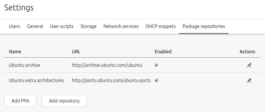
You can configure repositories in the ‘Package repositories’ tab on the ‘Settings’ page. Any enabled repository listed on this page will become automatically available to any subsequently deployed nodes.
MAAS further simplifies the addition of third-party repositories by also allowing the administrator to input their respective GPG keys here. This arrangement means that nodes will have instant access to these repositories (i.e. no need to import the keys into APT).
An added repository can be disabled and re-enabled using a toggle switch to the right of it.
Ubuntu package repositories
An Ubuntu package repository is a repository that makes available Ubuntu packages to computers able to connect to it over the network, whether that network is private or public (e.g. the Internet).
MAAS comes equipped with the official Ubuntu repository archive.ubuntu.com as well as the equivalent for architectures other than i386 and amd64: ports.ubuntu.com as is evident in the default configuration below:
Adding a third-party repository is elementary. Begin by basing the configuration on a line you would typically place in a system’s /etc/apt/sources.list file. For instance, for the Google Chrome repository, the line would look like:
deb http://dl.google.com/linux/chrome/deb stable main
You will also need the GPG public key that is associated with the private key that signed this particular repository. Typically, the project’s website is consulted to obtain this information. For this example, you could download the key like this:
wget https://dl.google.com/linux/linux_signing_key.pub
The key now resides in the saved file linux_signing_key.pub for later use.
To add this repository, then, hit the ‘Add repository’ button and fill in the fields using the gathered information. Note that the ‘Name’ is an arbitrary label to give the repository.
Before saving, the form should look very similar to this:
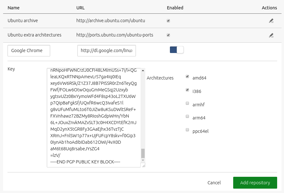
Click ‘Add repository’ to save the configuration.
A private repository can be built to assist with offline operations, based on the official repository. This repository can also contain custom packages.
Personal Package Archives (PPA)
A Personal Package Archive (PPA) is a Launchpad-based method for any individual (or team) to build and distribute packages for Ubuntu.
Adding a PPA is equally straightforward. Using the sosreport PPA as an example, first acquire the PPA’s address from its page on Launchpad:
ppa:canonical-support/support-tools
Like before, a public GPG key will be needed. Also get this from the PPA’s Launchpad page: ‘Technical details about this PPA’ > ‘1024R/9360754F’ > ‘9360754F’.
To add this PPA, then, hit the ‘Add repository’ button and fill in the fields. Before saving, the form should look something like this:
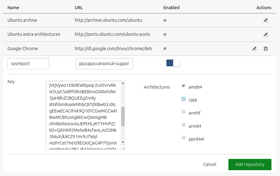
Click ‘Add repository’ to save the configuration.
See Launchpad PPAs for more information on PPAs.
NUMA/vNUMA
NUMA stands for “Non-Uniform Memory Access.” In this context, “non-uniform” means that any given CPU core can access its dedicated memory faster than the memory dedicated to other cores. A NUMA configuration groups core(s) and memory as a dedicated node, which reduces memory access times, so the core won’t spend a lot of time stalled in wait states – that is, waiting for access to data in memory, either because the memory is relatively far away (proximity) or because other cores have access to the same memory (shared memory). In other words, NUMA works better when the core has dedicated memory that is relatively close by.
In this context, “far away” could mean physical distance (more wire or a longer bus distance), more interceding processes (as in virtual machines), or both. The process of optimising thread and process scheduling so that the core running the code and the required data are close together is sometimes known as “creating affinity.” This affinity creates NUMA “nodes,” which can be addressed as black boxes from a symmetric multi-processing (SMP) point of view. Tasks are assigned to nodes to minimise overhead and wait states.
There is more flexibility in creating affinity when using virtual machines, because memory and core are constructs overlaid on existing hardware, rather than hard silicon. While this seems as if it might make SMP easier, in fact, it creates difficulties because of the nature of virtual machines and the potential number of interceding processes that manage virtual memory. For optimum performance, VMs should be aligned to a single NUMA node, so that resources are not split across nodes.
In practice, this means that VMs would be “pinned” to specific cores to create stability. While the user has the choice of how to pin VMs, MAAS provides visual information that helps the user see how VMs are allocated to physical hardware, and make adjustments if that arrangement isn’t (or turns out not to be) optimal.
If you want to dig deeper, there is a more through treatment of NUMA on Wikipedia.
SR-IOV
With traditional ethernet, a packet comes into the NIC and interrupt is fired for the one core assigned to handle NIC interrupts. That core has to go get the packet, find the destination MAC address or VLAN tag, then go interrupt the destination core – which has to get the packet and write it to the memory of the VM it’s managing. Statistically speaking, that’s basically two core interrupts for every incoming packet.
Many smart NICs are able to sort network packets into queues, based on MAC address or VLAN tag of the intended recipient, a technology sometimes known as “VMDq”. In these cases, each queue has its own interrupt, so each core gets interrupted only for its own packets. This arrangement is much faster than having one core assigned to handle all network interrupts. Even so, the hypervisor still has to copy every packet from the NIC to the VM, physically touching each packet.
With SR-IOV, it’s possible to have no core interrupts when packets come in. SR-IOV creates “virtual functions,” with dedicated queues for transmitting and receiving. Each VM is directly assigned hardware resources via a virtual function driver, which knows how to DMA-copy data directly between the NIC and the memory space of the relevant VM. Essentially, SR-IOV is like a “jumper wire” between the NIC and the VM, bypassing the core. This prevents interrupting the core when packets arrive for it, and significantly reduces the core workload when sending network packets.
For a deeper dive, try this SR-IOV presentation from Intel.
Isolating CPUs
For certain operations, it’s useful to shield a CPU from having to execute general system processes and take interrupts. These are sometimes referred to as “isolcpus,” more correctly described as booting a core with the isolcpus boot parameter. This parameter restricts the shielded core to processes assigned directly to it, avoiding sharing bandwidth with the general scheduler and preventing the core from taking non-specific interrupts.
When used with VMs, users can maximise performance by configuring isolcpus in the kernel, to prevent the general scheduler and other tasks from using bandwidth on your VM core(s).
Edge clouds
Edge clouds are designed to minimise latency, so that your cloud computing experience is nearer to real-time. The use of “edge” doesn’t specifically refer to the edges of the cloud, but to the machines that are at the “edge of the problem,” or more to the point, “the edge of the cloud that is closest to your application.” Sometimes these are separate clouds in your own data centre, though they can also be parts of a remote cloud that are closer to you in network terms.
There are a number of complex decision lops and optimisation algorithms used by edge clouds, but the primary purpose is low-latency computing where possible. If the servers closest to you (network-wise) can handle the load, they do; if not, they can call on other servers just a little further away.
Edge clouds can be planned and enhanced by using NUMA and SR-IOV techniques. NUMA can help you create SMP nodes on VM cores the shortest (network) distance away from your application. SR-IOV can, in general, reduce network latency even more by eliminating core involvement in network traffic. You can create virtual machines and assign NUMA nodes to minimise network latency, and then ensure that MAAS gives you NUMA tools to find out whether you’re achieving this sort of optimisation, and help you make decisions about how to adjust and improve over time.
Hugepages
Computer memory is addressed not as raw RAM, but as virtual memory. Assisted by the CPU’s memory management unit (MMU), the kernel maps virtual memory to a physical location. Virtual memory is divided into pages, which can be swapped in and out to disk during normal operation (hence the term “swap space”). When programs access memory, the CPU needs to know which physical page has the data, so it relies on the kernel’s “page table” to find the right virtual-to-physical address mapping.
Since this page table is big and slow, the CPU has a special buffer – the Translation Lookaside Buffer (TLB) – that caches address mapping. This means after the first access to a page, subsequent accesses are much faster. Since this buffer is implemented in hardware, for speed, the size is limited to, say, 4096 bytes.
When the core is accessing lots of pages, the speed advantage of the TLB can be lost. Hugepages allow one TLB entry to point to 2MB, instead of just 4096 bytes. With 512 TLB entires, typically, you can map 1GB of memory. Hugepages come with a catch, though: if you have to swap pages, it (obviously) takes longer.
There’s no tried and true formula for when to use them, but the key consideration is that you want to use most of a hugepage when you swap. Rather than using little sections of a hugepage, which would mean losing the performance advantage from constant swapping, you want to maximize the use of each hugepage. While there’s no simple, empirical way to calculate this answer, you can do it by trial-and-error observation.
MAAS provides the dashboards and tools necessary to monitor and adjust your use of hugepages, so that you can find the right balance.
Brief network tutorial
The following is a brief network tutorial, provided as a tool to synchronise understanding. Note that this tutorial covers mostly those terms routinely needed in the course of using MAAS.
DHCP
The Dynamic Host Control Protocol is a network management system in which a server (or group of servers) dynamically assigns IP addresses and other network parameters to a network device. This network device may or may not have the capability to provide its own IP address, although to take advantage of DHCP, the device must have been configured to seek out a DHCP server and accept an assigned IP address. Typically, a network administrator defines a range of reserved IP addresses from which the DHCP server can pull when assigning addresses.
DHCP operates using the four-step “DORA” model – Discovery, Offer, Request, and Acknowledge:
-
Potential DHCP clients broadcast a DHCPDISCOVER message on its attached subnet using destination address 255.255.255.255.
-
A connected DHCP server receives the DHCPDISCOVER message and sends a DHCPOFFER message, containing an IP address that the client may use.
-
The client replies with a DHCPREQUEST message, requesting the offered address.
-
The DHCP server responds with a DHCPACK (acknowledgement) which includes various important configuration parameters, such as the lease duration.
Of course, there is much more to DHCP, but what’s covered here should be sufficient understanding for using MAAS.
Client
In the client/server age, the lines between client and server are blurred and sometimes reversible. For the purposes of MAAS and general networking principles, we can define a “client” as a node that uses shared resources via a network. If that same client provides shared resources to other nodes, it could also be considered a server.
Server
A server is a node that provides shared resources to clients via a network. If that same server uses shared resources from other nodes, it could also be considered a client, but only in that context.
Network interface
A network interface, often referred to as a “network interface card” or NIC, is either a separate physical card connected to a node, a set of circuits embedded on a node’s motherboard, or a radio transceiver attached to a node in some way. All network connections require a NIC. The terms “port” and “adaptor” are also used to refer to a network interface.
MAC address
A MAC or “media access control” address is a unique address or “physical address” associated with a network interface. They are 48 bits in length, which allows for 280 trillion devices, arranged into six hexadecimal octets, separated by colons or dashes. Every computer in the world theoretically has a unique MAC address. You can identify a node’s IP address with the command ipconfig /all.
Network cable
Network cables are special cables that connect non-wireless-based nodes. They consist of our pairs of insulated, 24-gauge wire, colour-coded (solid/striped), usually in four colours: blue, green, orange, and brown. The matching colour pairs are twisted together, each pair at a different turn rate to prevent electromagnetic interference between pairs.
These twists must be maintained all the way up to the (RJ45) connector.
Even with insulation, careful twisting, and connector-termination, natural losses in the cable cause the network signals to become too weak to maintain reliable data rates after a certain length. In the case of Cat 5e cable, the maximum cable length is 100 meters to maintain 1Gb per second. For Cat 6, the max length to maintain 10Gb per second is 55 meters. These limits are overcome with repeaters, which amplify the signal and relay it to the next repeater or NIC.
Repeater
Technically, a repeater is a network signal amplifier with two RJ45 connectors which adds one maximum length (for the cable type) to the network connection or “run.” In practice, repeaters usually come in the form of hubs or switches, which can usually perform other functions as well.
Packet
A packet is a unit of network traffic. It may or may not represent a complete message.
Hub
Hubs essentially started as repeaters. While they may be able to connect more than two computers together (i.e., multiple RJ45 ports), they provide no improvement over simple bus networks, since every connected NIC must examine every packet. They are rarely used anymore.
Switch
A switch is a “smart” device that connects cables from nodes to make networks. Like a hub, a switch amplifies signals, that is, it acts as a repeater. Switches learn by induction which cables receive which IP addresses. Over time a switch will direct each packet only to devices which indicate that they will accept the addresses associated with those packets.
Network topology
Topology describes how nodes are connected to a network, specifically referring to the shapes made by the cables and the paths that packets can take. There are probably as many topologies are there are shapes, but here are five of the most common:
-
Bus topology: the most basic network topology, a group of computers connected to a single, long cable. In this configuration, every computer sees every packet. A hub network, for instance, is still a bus topology, because every machine sees every packet.
-
Star or switch topology: a group of computers connected to a switch. As the switch learns where packets are supposed to go, the star quickly evolves so that only packets are only seen by computers that are intended to receive the packet.
-
Backbone topology: a hybrid network configuration in which several stars are connected to a bus.
-
Daisy-chain topology: stars connected to stars, or more accurately, switches connected to switches.
-
Mesh topology: nodes with multiple interfaces and multiple connections. Useful where wide-area networks (WAN) where there would otherwise be lots of intermediaries. Not popular or particularly cost effective for LAN networks.
Patch panel
A patch panel is simply a 24- to 48-port panel of connectors that can link together three- to ten-foot cables. A patch panel allows jumpers from network runs to devices in racks, without putting strain and “cable creep” on long runs.
LAN
Besides topology, networks can also be classified by their size, range, or “reach.” One such classification is the Local Area Network (LAN), which connects computers in close proximity (about 300 feet).
WAN
A WAN (wide area network) is a network which connects LANs across large geographic distances, e.g., thousands of miles.
MAN
A metro area network or MAN connects LANs over a smaller area, like a city or urban footprint. Basically, if it isn’t really a WAN, but you can’t connect it with cables, it’s usually considered a MAN.
Network infrastructure
Network infrastructure is a catch-all term covering the physical components of a network, include cables, patch panels, switches, routers, hubs, and other associated network gear.
Router
A router is a device that transfers packets from one network to another. Unlike switches, which only ensure that pre-addressed packets get to the correct recipient machines, routers actually modify or encapsulate packets to ensure that they can travel on other networks to reach a remote destination.
Cloud-init
Cloud-init is the industry-standard method for initialising cloud instances, independent of platform. It allows you to automatically provision operating system images, bringing them to a fully running state. It also allows you to customize networking, storage, user space, applications, and various other components of a functioning system.
There are four stages of cloud-init action:
-
Local initialisation - this “as-early-as-possible” stage configures system elements that must be set up before the system can be made fully operational, such as networking configuration, including bridges, VLANs, bonds, and so forth.
-
Initialization - this second stage runs as soon as the network connections are up and running, taking care of custom storage configurations, disk volume expansion, block device setup and filesystem allocations.
-
Module configuration - stage three configures the necessary meta-tools to allow full system configuration, such as SSH, apt/yum, and NTP.
-
Module finalisation - stage four is the very end of the boot process, installing packages and executing any user-supplied configuration scripts.
These four steps combine (at least) four general datasources to bring an instance into being:
-
Disk image - the operating system for the instance; this is a bare-bones, uncustomized version of the chosen OS.
-
Metadata - this configuration information is supplied by the cloud provider, specifying things like disk images storage, networking, default users, and other basic customizations.
-
User data - data provided by end users or cloud administrators to initialise the instance. This completely optional data can be anything from shellscripts to highly-structured cloud-config data that trigger cloud-init’s built-ins.
-
Vendor data - data provided by cloud platform vendors; this is identical (in principle) to user data, but derived from a different source. In practice, vendor data usually handle things that users wouldn’t normally specify, such as mirror setup, NTP service management, etc.